How Do Mold Solutions Ensure Precision for Complex Part Designs?
Precision in complex molded parts comes from controlling geometry, material shrinkage, melt flow, cooling, tooling position, and measurement as one manufacturing system. A 30% glass-fiber PA6 grade, for example, can show about 0.25–0.30% shrinkage along flow but roughly 0.75–0.80% across flow, so one uniform cavity scale cannot accurately compensate for both directions. High-accuracy molds therefore combine DFM, flow and cooling analysis, CNC and EDM machining, controlled steel allowances, cavity-pressure checks, and CMM inspection. ISO 20457:2018 also treats molded-part tolerance as a manufacturing issue rather than simply a nominal CAD dimension.
A complex part can contain a 1.2 mm housing wall, 2.5 mm bosses, 0.8 mm ribs, side holes, sealing surfaces, snap features, and several datum-controlled mounting points. Each feature responds differently during filling and cooling. A cavity can measure correctly within 0.01 mm while the finished part still moves 0.10 mm after ejection because polymer contraction is not uniform.
That difference is why mold engineering begins before steel is machined. CAD data is reviewed for wall transitions, draft, rib thickness, boss location, unsupported cores, weld-line areas, gate access, ejection space, and dimensions that affect assembly. ISO 20457:2018 provides a formal framework for dimensional and geometrical tolerances on molded plastic parts and allows additional GPS specifications where function requires tighter control.
A tolerance written on a drawing describes the acceptable finished part; it does not tell the toolmaker how much local shrinkage, pressure deflection, fiber orientation, or cooling imbalance must be compensated inside the mold.
Once the functional dimensions are separated from less sensitive geometry, material behavior becomes easier to model. BASF data for a PA6-GF30 grade reports approximately 0.30% molding shrinkage parallel to flow and 0.75% normal to flow. Another PA6-GF30 processing sheet lists 0.25% parallel and 0.80% normal shrinkage under ISO 294-4 testing.
A 100 mm feature therefore cannot always be enlarged by one fixed percentage. Using 0.30% would suggest about 100.30 mm in one direction, while 0.75% would suggest about 100.75 mm in another. The 0.45 mm difference is far larger than the allowable dimensional error on many connector housings, bearing locations, optical carriers, or precision mounting structures.
That material behavior leads into gate and flow planning. Gate position controls where melt enters, how pressure falls across the cavity, where fibers align, and how effectively distant regions receive holding pressure. A long housing gated from one end may shrink differently from the same housing filled more symmetrically, even when both use identical cavity dimensions.
For reinforced polymers, flow direction also changes thermal expansion after molding. One BASF glass-filled PA6 grade lists a coefficient of linear thermal expansion of about 15 × 10⁻⁶/K parallel to orientation and 73 × 10⁻⁶/K normal to it between 23°C and 55°C. A 32°C temperature change can therefore produce very different movement depending on feature direction.
| Engineering input | What is checked | Typical dimensional concern |
|---|---|---|
| Wall thickness | Local fill and cooling time | Sink, bow, uneven contraction |
| Gate location | Flow length and pressure transfer | Orientation and local shrinkage |
| Rib/boss layout | Mass concentration | Position shift after cooling |
| Core length | Steel stiffness | Bore position or taper |
| Cooling layout | Surface-temperature balance | Flatness and twist |
| Slide position | Repeatability at mold close | Side-hole location and flash |
With those relationships mapped, machining allowances can be assigned more carefully. High-speed CNC works well for accessible 3D surfaces, pockets, inserts, and parting geometry, while sinker EDM reaches deep ribs, narrow slots, sharp internal transitions, and areas that rotating cutters cannot reproduce without excessive tool deflection.
Wire EDM is often used for through-profiles, precision inserts, lifter details, and shutoff components. Grinding then establishes accurate reference faces and mating surfaces. On molds requiring dimensional control near ±0.02 mm at selected steel features, machine accuracy alone is insufficient; electrode wear, cutter wear, heat in the workpiece, clamping distortion, and datum transfer between operations must also be measured.
Datum continuity matters more than quoting an impressive machine specification. If a cavity surface is finished on one setup and a mating insert is referenced from another poorly related surface, two individually accurate components can still create a positional error when assembled.
That is one reason complex molds frequently use inserts rather than machining every feature into one cavity block. A removable insert surrounding a connector, precision bore, sealing edge, or rib cluster can be produced and measured separately. If first-off samples show a 0.04 mm dimensional offset, modifying one insert is usually more controlled than altering a large cavity.
The same approach supports steel-safe construction. Material is intentionally retained on selected mold surfaces where later removal will move the molded dimension in the desired direction. First samples are measured, process conditions are stabilized, and only then is steel removed. For a tolerance window of 0.10 mm, an early correction of 0.08 mm without process data can consume most of the available adjustment range.
Moving mold components add another source of variation. Slides, lifters, hydraulic cores, collapsible cores, and unscrewing mechanisms must leave the molding position during ejection and return to nearly the same location on every cycle. A side core forming a 4.00 mm hole can produce dimensional or positional error if its locking surfaces wear or if injection pressure pushes the slide backward during filling.
Wear plates, tapered locks, guide surfaces, heel blocks, and hardened inserts are therefore selected around expected contact pressure and production volume. A mold intended for 1,000,000 cycles needs different wear planning from a prototype tool expected to make 5,000 parts. Service access also matters because a replaceable 20 mm insert is less disruptive than rebuilding a complete cavity after localized wear.
Mechanical repeatability still does not solve thermal variation, so cooling becomes the next part of dimensional control. Polymer close to a cold mold surface solidifies before material at the center of a thick boss. A 3.0 mm section may therefore continue contracting after an adjacent 1.2 mm wall has already become relatively rigid.
BASF processing data for PA6-GF30 lists a melt range of 270–290°C and a mold-temperature range of 80–90°C, with 280°C identified as an optimal melt setting for that grade. Temperatures are material-specific, but the data shows the scale of the thermal change occurring before a part reaches room conditions.
Cooling channels are not only there to shorten cycle time. Their distance from the cavity, diameter, water flow, circuit arrangement, and proximity to thick sections affect how evenly the part contracts.
Straight drilled channels may leave a tall core or deep pocket farther from coolant than nearby flat surfaces. Conformal channels can follow complex cavity geometry more closely where the tool construction and production volume justify them. The engineering target is not the lowest possible temperature; it is a repeatable temperature distribution that limits uneven contraction.
Long-term dimensional movement also needs consideration. BASF testing on POM compared shrinkage after 1 hour, 14 days, and 60 days at room temperature and also evaluated parts after 24 hours at 120°C. The published data shows that post-crystallization can continue changing dimensions after molding. Measurements taken immediately after ejection therefore may not represent the dimensions seen later in service.
Moisture adds another variable for polyamides. BASF lists equilibrium moisture absorption of roughly 1.9–2.3% at 23°C and 50% relative humidity for one PA6-GF30 grade, with saturation water absorption around 6.3–6.9%. Inspection conditions should therefore state conditioning time, temperature, and humidity when very small dimensional tolerances are involved.
After thermal behavior is controlled, injection pressure must be considered. Long core pins, thin cavity walls, unsupported inserts, and large projected areas can move elastically under pressure. A toolmaker can machine a bore-forming core accurately, yet melt pressure acting unevenly around that core can shift its position during the actual shot.
Support geometry, steel section thickness, gate placement, mold locking, backing plates, and core length are reviewed together for this reason. A dimensional error that appears only at higher injection or holding pressure should be studied before the cavity is altered; otherwise a process-related movement may be incorrectly treated as a machining error.
Process measurement helps separate the two. Cavity-pressure sensors can show filling, transfer, packing, and gate-seal behavior inside the mold rather than relying only on machine settings. If 30 consecutive shots produce similar pressure curves but a bore remains 0.06 mm undersized, the tool geometry or material compensation deserves attention. If the pressure curve changes with the dimension, the molding process needs investigation first.
Venting belongs in the same review because trapped air changes local filling and packing. Narrow ribs, end-of-fill regions, and deep pockets can trap gas, preventing the melt from reaching the same pressure profile on every shot. Vent depth is selected for the polymer so gas can leave without allowing melt to form flash.
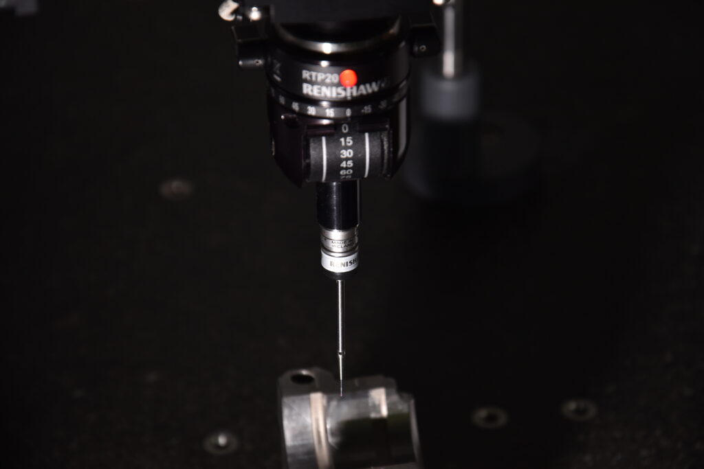
Dimensional inspection then connects actual parts back to CAD. A CMM can measure hole position, profile, flatness, perpendicularity, datum relationships, and distances that calipers cannot adequately describe. Optical scanning can add surface comparison where free-form geometry involves hundreds or thousands of measurement points.
For a first mold trial, measurement should focus on function rather than producing a long report of low-importance dimensions. A 150 mm housing may have 80 drawing dimensions, but perhaps only 12 control connector position, sealing, assembly alignment, and mating surfaces. Repeating those 12 measurements across a sample of 10–30 conditioned parts provides more useful process information than measuring one part once.
The resulting deviations guide controlled tool correction. Dimensions consistently offset across stable molding conditions can be adjusted in steel; dimensions that move noticeably with packing pressure, mold temperature, or cooling time should first be addressed through processing or thermal changes. Recording every correction also prevents later maintenance work from returning an insert to its original CAD value when the production-qualified geometry intentionally differs from nominal.
Companies using a structured approach such as Qlution Injection Solutions can combine mold design, machining, sampling, dimensional inspection, and production feedback in one tooling workflow. The practical benefit appears when a 0.05 mm issue can be traced to a specific insert, process condition, cooling region, or material direction instead of changing several variables at once.
Production qualification should then use more than one good sample. Dimensional capability is normally evaluated over repeated cycles after temperatures and material conditions have stabilized. A batch of 30 parts, for example, can expose repeatability that three hand-selected samples will miss, while later checks after 10,000 or 100,000 cycles can show whether slides, vents, gates, and shutoffs are beginning to wear.
Maintenance data belongs beside measurement data for the same reason. If flash appears after 250,000 cycles, bore location moves 0.03 mm, or cavity pressure gradually changes after vent cleaning intervals are extended, maintenance teams can compare those observations with earlier qualified conditions rather than relying on visual judgment.
A precision mold for a complex part is therefore developed through repeated comparison among CAD dimensions, predicted shrinkage, measured steel, conditioned samples, process data, and wear history. When a reinforced polymer can shrink about 0.30% in one direction and 0.75% in another, while temperature and moisture continue affecting dimensions after molding, maintaining a 0.05–0.10 mm functional tolerance depends on controlling the complete manufacturing route rather than cavity machining alone.